This project is part of my personal project turned side hustle, Bottle Grab, and on this page, I’m specifically showcasing the development and design for injection molding of the bottle hand, the part that holds and “hands-off” bottles to riders.
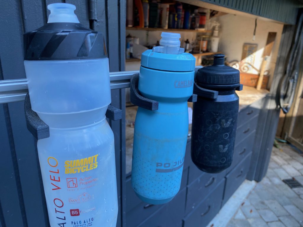
The bottle hand utilizes the neck that is present on most cycling bottles to suspend the bottles and allow them to be taken while riding at speed. A portion of the neck rests on the bottle hand after the bottle is slid into the groove. It rests there until it is grabbed, taken the opposite way it was slid into the groove. The bottle hand is designed to be fastened with an M-5 screw to 20-20 aluminum framing.
I initially had brainstormed whether I needed a custom geometry for a cycling bottle or a collar that attaches to a standard bottle. I decided that for product adoption it needed to be compatible with the vast majority of existing cycling bottles. Luckily, the neck of the cycling bottle was the perfect mating feature. The neck is there to interface with a “hook” feature on the top end of a bottle cage that helps prevent the bottle from flying off a bike in the event of heavy road bumps.
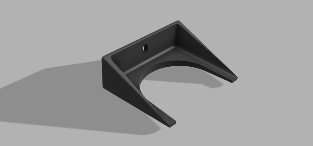
To design the part, I used my at home 3D printer, a Creality Ender 3 S1 Pro, to test different groove diameters for bottle neck fit. All cycling bottles have a standard OD of around 72 mm in order to fit into most bottle cages, but the dimensions of the neck vary. I measured the neck dimensions of every cycling bottle in my parents house, which there were many different kinds, and came up with dimensions to prototype for the groove of the bottle hand. After a few iterations, this is the geometry I came up with:
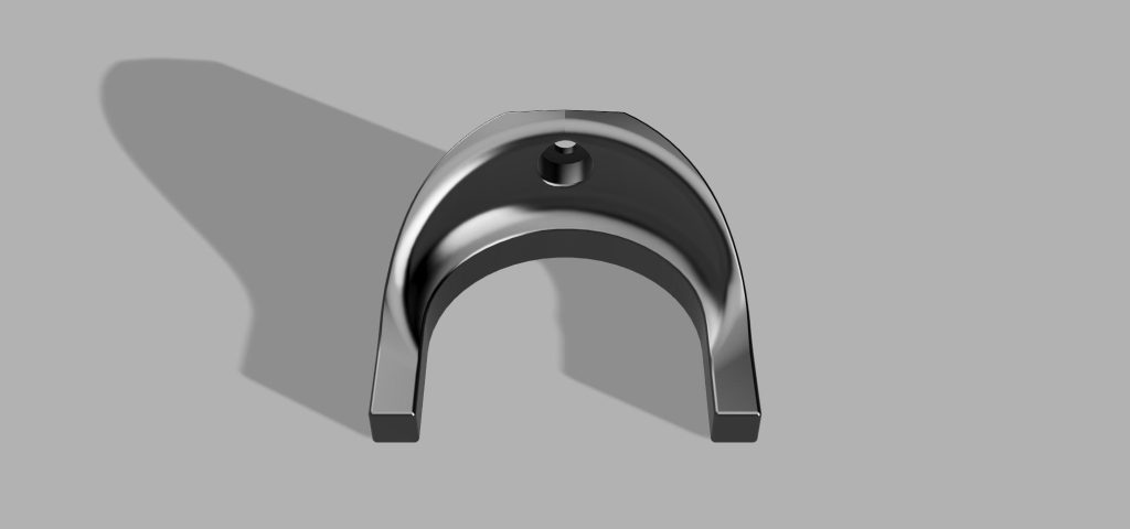
The groove contacts the bottle neck, holds it in place, and allows it to be taken at speed. The vertical arch that connects the fastener hole to the groove serves two functions:
- It acts as a rib to provide stiffness and strength to the part as it transitions from a horizontal facing plane where the fastener hole is to a vertical facing plane where the groove is loaded with a bottle.
- It retains the OD of the bottle above the neck, keeping the bottle in the bottle hand when incurring light to moderate disturbance.
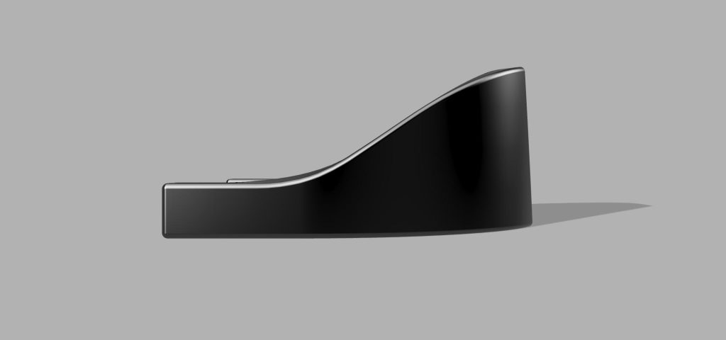
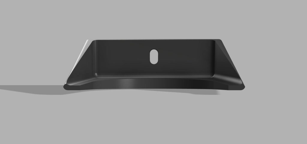
The arms that extend from the groove while not necessary for holding the bottle in place and to be taken are there to also retain the bottle during light to moderate disturbance. The back of the bottle arm is drafted 5 degrees toward the groove plane such that the bottle slides back into the groove due to the force of gravity when incurring disturbance. The arms add additional landing for the bottle to fall back onto during disturbance.
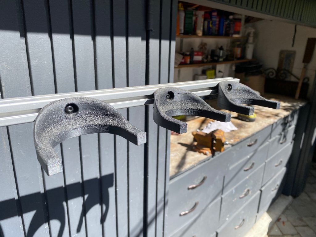
I printed these parts from a chopped carbon fiber and ASA printing material. I chose ASA because it’s UV stable and impact resistant in case of wear and tear during travel and perhaps a tip of the stand when the sand bags are not installed. I’ve printed with chopped carbon fiber before, and I was intrigued to do it with my at home printer. I also like to err on the side of over engineering, so between the CF + ASA and overly reinforced geometry, the bottle hands were quite strong and stiff. I left the stand out for a month or two between November and January to confirm how not only these printed bottle hands but the aluminum framing would hold up, and through some inclement weather, it held up without any signs of deterioration.
These bottle hands were used in early demos and races, including the neutral water feed at Ward’s Ferry road race where four Bottle Grabs fed over 75 riders.
Each of these CF+ASA 3D printed bottle hands took over 4 hours to 3D print. Did I mention they were printed at 100% infill due to the constraints of the material? Thus, this is not a scalable part or manufacturing method.
I decided to learn how to design parts for injection molding to solve this problem and learn a valuable skill in the process. I read extensive design guides on Protolabs website and went to work. I redesigned the bottle hand to adhere to wall thickness guidelines for injection molding to avoid
sink marks, warping, and internal voids. I followed guidelines for edge radii for part release, plastic flow, stress concentrations, and mold machining; draft angle guidelines for part release (confirmed by using Autodesk Fusion 360’s built in draft analysis), and ribbing guidelines. The result is a more simply designed bottle hand that is just as capable and ready for mass production.
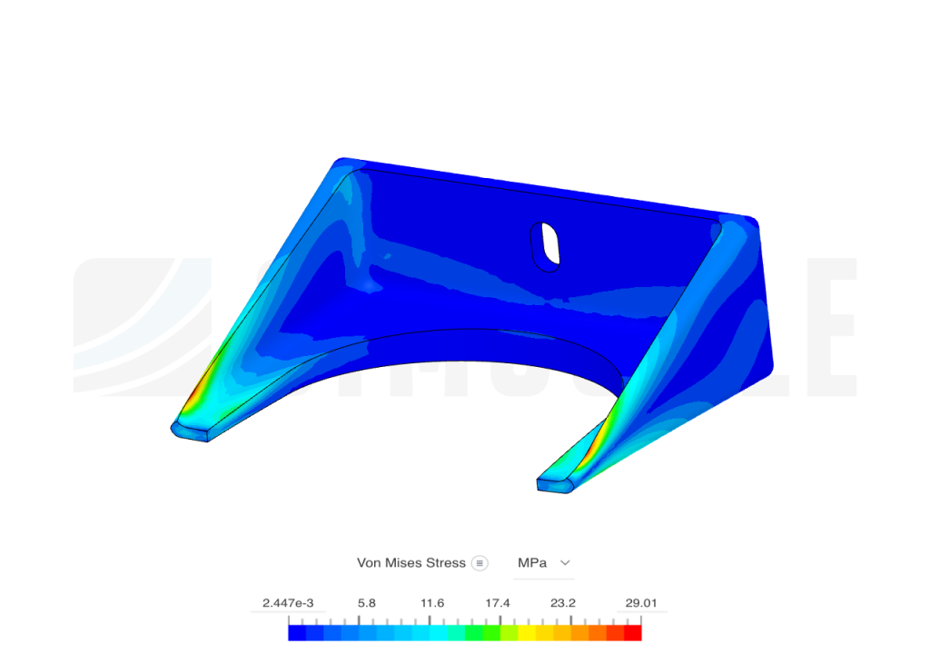
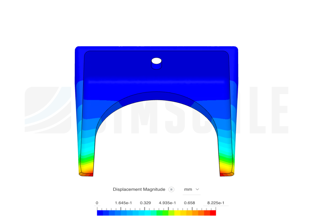
I used SimScale to run FEA to confirm the part’s mechanical function. I ran a static simulation, at first designing the part to worst case hold the largest cycling bottle on the market (~34 oz) full of water, electrolytes, and carbs. I evaluated different materials for injection molding, including ASA, Polycarbonate, PEEK, LCP, and PEI using Protolabs guide to injection molded materials. After running the simulation, I learned my initial designs were over-engineered, though intuitively it didn’t sit well with me. I 3D printed a thinner version of the design from PLA and tested it out, and I didn’t like how flimsy it felt despite it’s ability to hold and hand off heavy bottles. Not long after while thinking things over before bed one night, I realized that the worst case loading is not holding a heavy bottle but rather forces from taking the bottle. At Ward’s Ferry, 100% of the hand-offs were successful, but I’d say 95% of them were ideal, meaning they did not knock off other bottles or cause high disturbance to the stand. One rider in particular of the over 75 racers kept pulling down on the bottle as he took it, flexing the arm of the stand down. Once he cleared the bottle from the bottle arm groove, the stand arm would rebound and send the two other bottles on the arm flying. The bottle hand needs to be able to withstand these kinds of forces.
One 34 oz bottle full of water, electrolytes, and carbs weighs around 12 N. The highest recorded pull strength of a human male while sitting down was 400 N. After doing some estimating of what to expect from a rider taking a bottle, I decided to run the FEA and see what the highest recorded stress values would be for various downward forces. Given what I saw, the variation of pull down forces expected from riders, and the very narrow margin for changing the geometry of injection molded parts, I decided to make the geometry incorporate the maximum wall thicknesses possible and use a strong injection molded plastic designed for outdoor applications and impact resistance, PEI, specifically the Ultem Resin 1000. This plastic is used for automotive, industrial, and aerospace applications, in addition to outdoor and lawn & landscape applications. The captures of the simulations below include boundary conditions of a 50 N downward force at the tips of the arms and a fixed back surface of the part where it contacts the 20-20 framing.
I worked with Protolabs to get a design analysis for injection molding. A few design changes were necessary – it turned out sections of the ribs were too thin while the thickest parts where the bottle landing meets the fastener plane were too thick. Protolabs was also concerned about using PEI due to high cycle temps and costs.
I then teamed up with a former colleague from Arris who is a molding and tooling afficionado, Justin Church, who started a consulting business involving injection molding. Justin recommended a stronger and cheaper alternative to PEI – PBT GF 20% while maintaining UV and impact resistance and stiffness! I was curious about glass fiber reinforced polymers but found them intimidating, but luckily Justin came to the rescue. He did a great job getting me a fantastic quote for a single cavity mold with this design.
I’m hoping to grow Bottle Grab to the point of placing this order!